
 ←Index
by Professor Petabyte
Sorry Mr Vogon, but you are way very wrong about that! Resistance is vital - Essential to almost every electronic gizmo ever created, and much of it come from resistors.
The questions that bug most budding electronics engineers are how much to use, and how do resistors interact?
If you want to reproduce the experiments on this page yourself, you will need:-
An ohm (symbol:Ω) is the standard unit of electrical resistance in the International System of Units (SI). In simple termsa an Ohm measures how much a material or component resists the flow of electric current.
i.e. 1 Ω = 1 volt / 1 ampere
Think of electricity like water in a pipe:
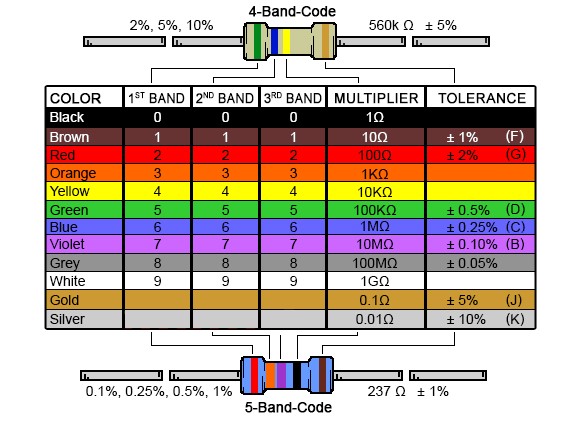
The resistance rating of a resistor is shown using either 4 or 5 coloured bands on the body of the resistor.
A surface mount resistor is a tiny rectangular ceramic body with silver conductive edges on either end. Also referred to as surface mount technology, an SMD resistor offers advantages in saving space on printed circuit boards (PCBs). It features the resistance value code printed onto it, where there is space. Surface mount technology supports microelectronics by allowing more components to be placed closer together on the board. This leads to designs that are more lightweight and compact. The process for SMT production setup is faster when compared to through-hole technology. These are howver mostly used in industrial production, not development scenarios.
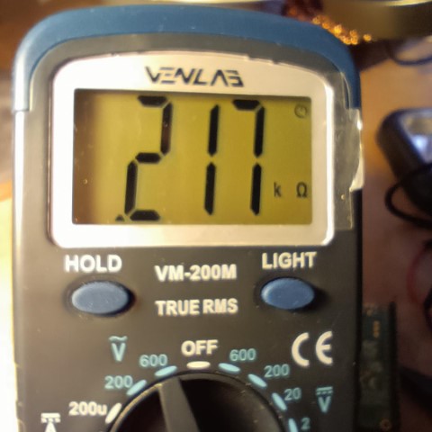
Resistors tend not to be perfect, but this is to be expected due to factors like manufacturing tolerances, natural variations in material, temperature etc. To start with I measured the actual resistance of the resistors as shown in the table below. Note how the Actual resistance varies slightly from the Rated resistance.
| Rated Resistance | Actual Resistance | Deviation |
|---|---|---|
| 220Ω | 217Ω | 98.64% |
| 1kΩ | 999Ω | 99.9% |
| 1000Ω | 1003Ω | 100.3% |
| 10,000Ω | 9,990Ω | 99.9% |
Resistors are typically 1% to 5% above or below the stated resistance value, so these (actual resistance) values are OK.
...meaning one after another in a line to that electricity has to flow through each resistor before reaching the next one.
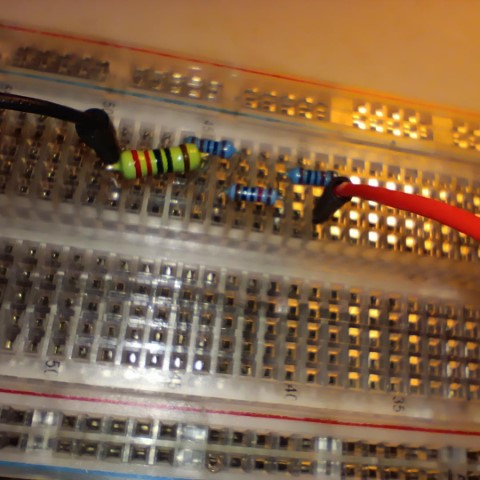
Yellow line shows path current must take.
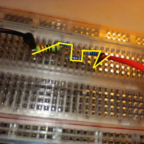
Here we see all four resistors, one after another. To calculate their resistance just add the ratings together:-
220Ω + 1,000Ω + 1,000Ω + 10,000Ω = 12,220Ω
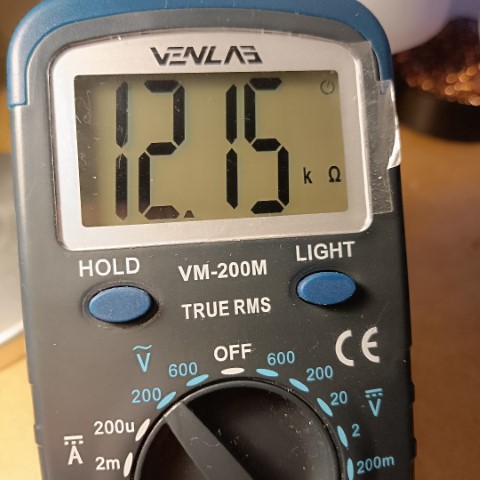
Measuring this the actual resistance was 12,150Ω, or 99.42% of the calculated figure of 12,220Ω.
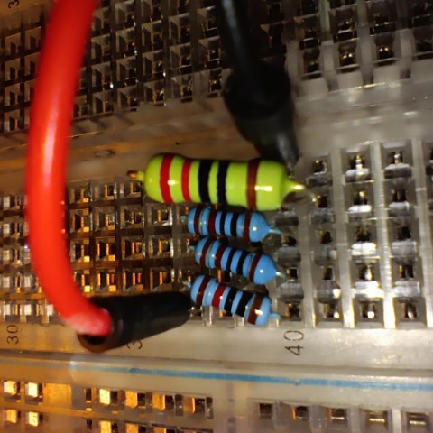
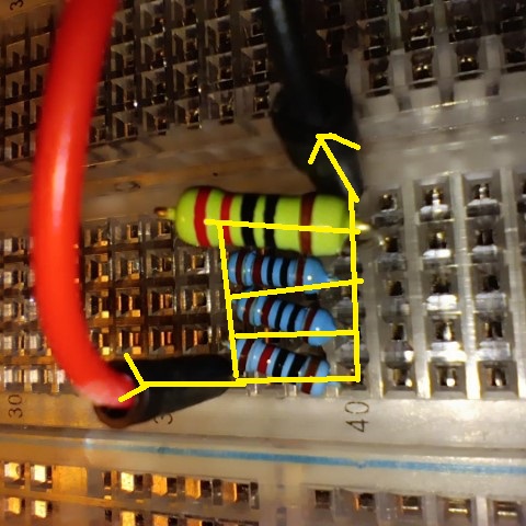
...meaning the current can flow through any of four routes, each going through one resistor only.
Yellow line shows paths current can take.
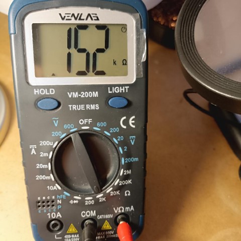
Here we see all four resistors, in parallel. To calculate their total resistance the maths is just a little more complex *:-
1/R = (1/217) + (1/999) + (1/1,003) + (1/9,990) =>
1/R = 0.0046_ + 0.001 + 0.0099_ + 0.001_ =>
1/R = 0.0067_ =>
R = 149Ω
* N.B. These figures are the actual measured resistance of each resistor, not the rated resistance value.
Measuring this the actual resistance was 152Ω, or 102.0% of the calculated figure of 149Ω.
In general, no it's not inherently expected that adding more resistors in parallel will always increase the percentage difference between calculated and measured resistance. However, in practice, under certain conditions, it can seem that way, and here's why:-
THEORETICALLY
When resistors are in parallel, the total equivalent resistance is given by the formulea
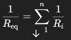
As you add more resistors in parallel:
IN PRACTICE
There are some things that might cause a growing discrepancy:
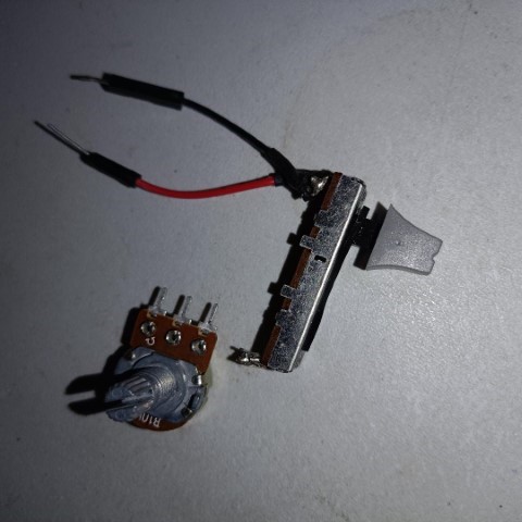
There are two main types of 'mechanical resistors' or 'potentiometers - Knobs and Sliders, as seen here.
but there are several other 'non-mechanical' types included below:-
Often rreferred to as 'pots', enable fine control of resistance by using a dial or sliding element. The resistive element of a potentiometer can be adjusted using a wiper, controlled by turning a knob or moving a slider. Along with the “wiper” terminal, potentiometers have two additional terminals, typically referred to as “input” and “output” terminals. Two common types of potentiometers are linear and rotary. Linear potentiometers find use in applications like volume control on audio devices, while rotary potentiometers are employed in settings requiring rotational adjustment, such as tuning radio frequencies. They come in various forms, including carbon film and metal oxide variants.
Rheostats are specialized variable resistors designed with only two terminals. While potentiometers are used to control voltage, the primary use of rheostats is to control current in a circuit, adjusting electrical resistance as needed. The two terminals are connected in series with a load (e.g., a light bulb or motor). Adjusting the position of a wiper along the resistance wire changes the resistance in series with the load, thus controlling the current. Common applications of rheostats include dimmer switches for lights and motor speed control.
Photoresistors, also known as light-dependent resistors (LDRs), are two-terminal resistors that change in response to light levels. An LDR exhibits a decrease in resistance as light intensity increases, enabling it to sense and react to environmental light changes. This property makes an LDR ideal for applications like automatic lighting control and light-sensitive alarms.
Thermistors are temperature-sensitive resistors with two terminals that exhibit changes in electrical resistance with temperature fluctuations. They are classified into two primary types: negative temperature coefficient (NTC) and positive temperature coefficient (PTC). NTC thermistors decrease resistance with increasing temperature, while PTC thermistors exhibit the opposite behavior, making them essential in temperature control systems, such as thermostats, and are vital for temperature compensation in various electronic circuits.
These are constructed by winding a resistive wire around an insulating core, are known for their precision and ability to handle high power levels. Although having both fixed and variable variations, variable wirewound resistors allow for the length of the resistance wire included in the circuit to change, altering the resistance. Wirewound resistors also have two terminals. Wirewound resistors are used in applications that demand precise resistance values, such as in precision instruments and high-power electronic circuits.
Varistors, also known as voltage-dependent resistors or VDRs, are specialized two-terminal variable resistors designed to protect electronic circuits from voltage spikes and surges. They exhibit a high electrical resistance under normal conditions but rapidly decrease their resistance when exposed to excessive voltage. This behavior allows varistors to shunt excessive voltage away from sensitive components by allowing high current to flow through the varistor instead. Varistors find use for surge protection in electronic systems.
| Type | Usage | Technical Aspects |
|---|---|---|
| 1. Potentiometer | Volume control, tuning, and adjustment | Wiper, resistive element material |
| 2. Rheostat | Current control, dimming, motor speed | Two-terminal design for current control |
| 3. Photoresistor | Light-dependent circuits, alarms, cameras. | Photoconductive; Light sensitive |
| 4. Wirewound Resistor | Precision applications, high-power circuits | Resistive wire winding gives good precision |
| 5. Thermistor | Temperature control, e.g. ovens | Temperature-sensitive resistance |
| 6. Varistor | Surge protection, voltage spike mitigation | Voltage-dependent switching for circuit protection |
Resistor packs are very useful items. Where you need a bank of resistors of the same value (e.g. to protect a bank of LEDs) a resistor pack can be a very quick and convenient way to add many resistors to your circuit, especially if developng on a solderless breadboard.
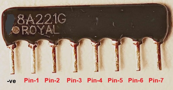
Don't be fooled by the photo close-up - Although this thing looks like a 2foot wide lump of iron that spent a week in the sea it is infact only 2cm wide, and hasn't spend any time in the sea at all. The dot just next to the word 'Royal' indicates where the 'common' pin is. The other seven pins are the 'other side' of the resistor.
Having only eight pins means this resistor pack can limit voltage to only seven items. In the video below it can be seen limiting voltage to a bank of LEDs, however, because the LED bank has ten LEDs, three 220Ω resistors can also be seen, limiting voltage to those LEDs that the resistor bank cannot (because it only has seven pins plus the common pin).
So to summarise, the common pin of the resistor bank is connected to ground, and the other seven pins are connected to the cathodes of the first seven LEDs in the LED bank. The cathodes of the final three LEDs in the LED bank are connected to 'normal' 220Ω resistors. The other side of the LED bank (the anode-side) is connected to ten GPIO pins on the Raspberry Pi Pico (one pin per LED), which are being periodically energised in sequence to light the LEDs. The Micropythion code for this is shown below.
from machine import Pin

import time


# Define the list of pin numbers to use

pin_numbers = [16,17,18,19,20,21,22,26,27,28]


# Create an array (list) of Pin objects

pins = [Pin(pin_num, Pin.OUT) for pin_num in pin_numbers]


#Repeat forever

while True:

    # Turn all pins ON with short delay between each one

    for pin in pins:

        pin.on()

        time.sleep(0.01)


    # Turn all pins OFF with short delay between each one

    for pin in pins:

        pin.off()

        time.sleep(0.01)