Pure Electronics
 ←Index
Integrated Circuits
by Professor Petabyte
Introduction
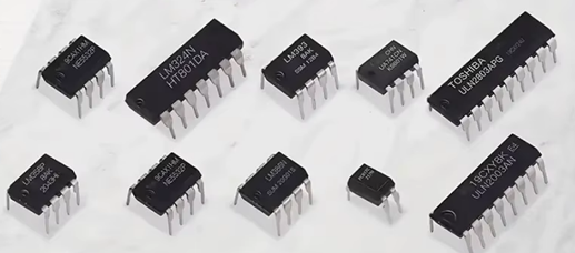
Inegrated Circuits are what most people are referring to when they say "Microchips". They are typically (although not neccessarily) black rectangular components with metal pins protruding from both side, like those in the picture. Others are square with pins along all four sides, although there are typically Micro-processors, a different type of integrated circuit.
Integrated Circuits are so called because they typically contain several miniturised components with apprpriate connections between those components, and also to the pins along each side of the IC. It is possible to use full sized components to replicate the functionality of the IC, but that is the point of ICs - to provide little short-cuts, miniaturisation and convenience to device building. Very often a data sheet will include a circuit diagram of the components inside the IC as part of the explanation of how it works.
ICs with very large numbers of internal components include microprocessors, microcontrollers, FPGAs (Field-Programmable Gate Array), and memory chips. These components are typically found in computers, smartphones, and other complex electronic devices.
Microprocessors and Microcontrollers:
These ICs are the brains of many electronic devices, responsible for processing data and controlling operations. They can contain billions of transistors, allowing them to perform complex tasks.
FPGAs (Field-Programmable Gate Arrays):
These are programmable ICs that can be configured to perform various functions after manufacturing. They are often used in applications where custom hardware is needed, such as in aerospace and AI.
Memory ICs (RAM, ROM, Flash):
These ICs are used for storing data, both temporarily and permanently. They can also contain millions or even billions of transistors, allowing them to store large amounts of information.
Application-Specific Integrated Circuits (ASICs):
These are custom-designed ICs for specific applications, such as cellphones. They can incorporate both analog and digital functions, including sensor interfaces and memory
Standard ICs
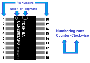 There are many types of standard ICs, each type serves a particular purpose. They most (but not all) have a similar general layout. At one end is a mark or indentation that indicated where the 'top' of the IC is, and the pins are numbered anticlockwise from that point. Where the indicator is not a central notch, it usuallu is closest to pin 1 of the IC. The type of IC, and sometimes (not always) the name of the manufacturer is printed on the IC.
It is important to know where the top of the IC is to determine which pin is which. If the IC were inserted upside down for example, pin 1 would become pin 18, pin 2 would become pin 17, and so on. Sometimes the top mark is a cut-out or notch in the plastic, but it can just be a dot painted on.
Where an IC is mounted on a breadboard it is important that the IC straddles the center line, otherwise pins would be connected which should not be.
The IC manufacturers usually publish a "Data Sheet" for eacxh of their products, which explains operation, capabilities and tolerances etc.
Where possible for each of the ICs listed below there is a link to data sheet. Data sheets are neccessarily very technical documents, often detailed and quite lengthy, but they do hold the information vitel to understanding the IC and how to integrate it into a a working system.
IC Suffixes
The suffixes like 'N', 'P', 'D', etc., on IC part numbers (e.g., LM324N, LM358P) usually indicate the package type or manufacturer-specific info, not changes in electrical function. Here's a breakdown:
Common IC Suffixes and Their Meanings
| Suffix | Meaning | Example | Notes |
|---|
| N | DIP (Dual In-line Package) | LM324N | Through-hole package, easy for breadboarding. |
| P | Often also DIP (depends on maker) | LM358P | Used by some manufacturers like Texas Instruments. |
| D | SOIC (Small Outline IC) | LM358D | Surface-mount package for compact designs. |
| T | SOT-23 or similar small package | TLV2372T | Ultra-small surface mount. |
| R | TSSOP or SSOP package | LM324DR | Thin surface-mount variant. |
| A/B | Grade or temp range | LM324A | 'A' often means higher precision or range. |
| M | Military or extended temperature | LM358AM | Used in harsher environments. |
Manufacturer-Specific Differences
Some suffixes are branding conventions:
- TI uses 'P' for PDIP, 'D' for SOIC, etc.
- STMicroelectronics and others might use 'N' for DIP.
Pin Numbering on ICs - How to Identify Pins
Pin numbering on ICs (integrated circuits) follows a standardized layout, depending on the package type (e.g., DIP, SOIC, TSSOP). Here’s how to read them:
- Start at the top left (next to a notch or dot).
- Number goes counterclockwise around the chip.
Some Common Intergrated Circuits
IC INDEX
Note: The number of different ICs available today is in the low thousands - likely between 2,000 and 5,000 distinct part numbers, depending on how you define "different" and what is included e.g., families, variants, packaging types, etc. This is therefore necessarily a very tiny handful of commonly used ICs, perhaps around 0.5% of those available.
| NE555 - Timer |
LM324N - Quad Operational Amplifier |
LM358P - Widely used Dual Operational Amplifier |
| LM393P - Dual differential voltage comparator |
UA741 - Classic general-purpose operational amplifier |
PC817 - Optocoupler (Optoisolator) |
| ULN2803 - Darlington Transistor Array (8-Channel) |
ULN2003APG - Darlington Transistor Array (7-Channel) - |
LM386 - Audio Amplifier |
| NE5532 - Low-Noise Dual Op-Amp |
|
|
NE555
Mouseover to Zoom
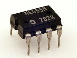
The NE555 IC is a versatile integrated circuit primarily used for generating timing signals, delays, and oscillations. It can operate in monostable (one-shot), astable (continuous oscillation), and bistable (flip-flop) modes. These modes allow it to be used in a variety of applications, including pulse generation, timers, and even as a buffer.
Key Functions:
- Time Delays:
In monostable mode, the NE555 can generate a single, precise pulse of a specific duration when triggered.
- Oscillations:
In astable mode, it produces a continuous square wave output, allowing for frequency generation.
- Pulse Generation:
The NE555 is commonly used to generate pulses for various applications, like digital clock signals or controlling other circuits.
- Flip-Flop:
In bistable mode, it can act as a simple flip-flop, storing a binary state (high or low).
- Buffer:
The output can also be used as a buffer, inverting the input signal.
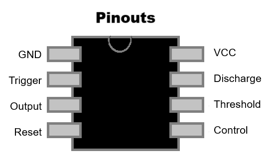
Pinout (8-pin DIP):
Mouseover to Zoom
- GND
- Trigger
- Output
- Reset
- Control
- Threshold
- Discharge
- VCC
Operating Modes:
- Monostable:
Produces a single pulse of a specific duration after being triggered.
- Astable:
Generates a continuous square wave output, providing a timing signal.
- Bistable:
Acts like a flip-flop, storing a binary state (high or low).
Summary:
In summary, the NE555 IC is a versatile timer IC that can be used for a wide range of applications, including generating timing signals, delays, and oscillations, making it a popular choice for many electronic circuits.
Links:
IC Index
-
LM324N
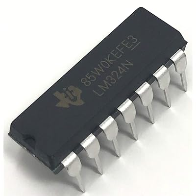
Mouseover to Zoom
The LM324N is a widely used quad operational amplifier (op-amp) IC (integrated circuit) manufactured by various companies such as Texas Instruments, ON Semiconductor, and STMicroelectronics. It is known for its low cost, wide supply voltage range, and suitability for general-purpose analog applications.
Key Features of LM324N:
- Op-Amps: Contains four independent op-amps in one 14-pin DIP (Dual Inline Package).
- Single Supply Operation: Works well with a single power supply as low as 3V and up to 32V (or ±1.5V to ±16V for dual supply).
- Low Power Consumption: Suitable for battery-powered devices.
- Internally Frequency Compensated: Simplifies design by eliminating the need for external compensation components.
- Wide Bandwidth: Approximately 1 MHz gain-bandwidth product.
- Large Output Voltage Swing: Close to ground in single supply mode, which is helpful for single-supply systems.
- Short-Circuit Protection: The output is protected from short circuits to ground or VCC.
Package:
The "N" suffix in LM324N indicates the DIP (Dual Inline Package) version, commonly used in prototyping and through-hole circuit designs.
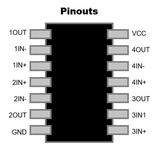
Pinout (14-pin DIP):
Each op-amp has:
- One non-inverting input (+)
- One inverting input (-)
- One output
Mouseover to Zoom
Here is a pinout diagram of the LM324N. ALWAYS refer to manufacturers datasheet for full specification.
- 1OUT: Output of op-amp 1
- 1IN-: Inverting input of op-amp 1
- 1IN+: Non-inverting input of op-amp 1
- 2IN+: Non-inverting input of op-amp 2
- 2IN-: Inverting input of op-amp 2
- 2OUT: Output of op-amp 2
- GND: Ground
- 3IN+: Non-inverting input of op-amp 3
- 3IN-: Inverting input of op-amp 3
- 3OUT: Output of op-amp 3
- 4IN+: Non-inverting input of op-amp 4
- 4IN-: Inverting input of op-amp 4
- 4OUT: Output of op-amp 4
- VCC: Positive power supply (3V-32V typical)
Typical Applications:
- Signal conditioning
- Sensor interface
- Oscillators
- Active filters
- Comparators
- Audio preamplifiers
- General-purpose analog processing
Design Considerations:
- Not a rail-to-rail op-amp: The output does not reach the positive supply rail.
- Moderate slew rate: ~0.5 V/µs, meaning it's not ideal for fast-changing signals.
- Input offset voltage may require calibration in precision applications.
IC Index
-
LM358P
The LM358P is a widely used dual operational amplifier (op-amp) IC from Texas Instruments, designed for general-purpose analog signal processing. It integrates two independent, high-gain, internally frequency-compensated op-amps into a single 8-pin Dual In-line Package (DIP), making it suitable for a variety of applications.
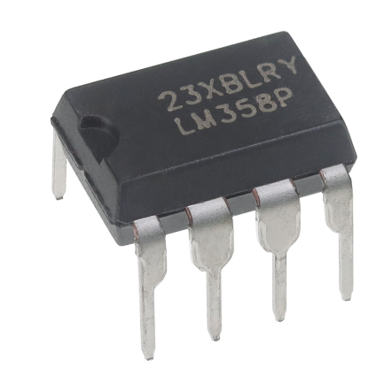
Mouseover to Zoom
Key Features
- Dual Op-Amps: Contains two independent op-amps in one package
- Wide Supply Voltage Range: Operates from a single supply of 3V to 32V or dual supplies of ±1.5V to ±16V .
- Low Power Consumption: Typical supply current is 500µA per amplifier .
- Common-Mode Input Range Includes Ground: Allows direct sensing near ground in single-supply applications
- Internally Frequency Compensated: Simplifies circuit design by eliminating the need for external compensation components.
- Short-Circuit Protected Outputs: Enhances reliability in various applications.
Electrical Characteristics
- Gain Bandwidth Product: 700kHz .
- Slew Rate: 0.3V/µs .
- Input Offset Voltage: Typically 3mV .
- Input Bias Current: Typically 20nA .
- Output Current per Channel: Up to 40mA .
Package Information
- Package Type: 8-pin PDIP (Plastic Dual In-line Package)
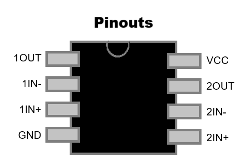
Pin Configuration (Top View)
Mouseover to Zoom
- 1OUT: Output of op-amp 1
- 1IN-: Inverting input of op-amp 1
- 1IN+: Non-inverting input of op-amp 1
- GND: Ground
- 2IN+: Non-inverting input of op-amp 2
- 2IN-: Inverting input of op-amp 2
- 2OUT: Output of op-amp 2
- VCC: Positive power supply
Typical Applications
- Signal Amplifier; Amplifies weak analog signals (e.g., from sensors like temperature or light sensors).
- Voltage Follower (Buffer); Provides high input impedance and low output impedance to prevent signal loading.
- Comparator; Compares two voltages and outputs a digital signal (though not optimized for high-speed logic-level switching).
- Active Filters; Used in low-pass, high-pass, band-pass, and band-stop filter designs.
- Oscillators; Can be used to generate square, triangular, or sine wave signals.
- Integrator/Differentiator; Analog computing functions useful in control systems or waveform shaping.
- Sensor Signal Conditioning; Amplifies and cleans up signals from analog sensors (e.g., gas, pH, or pressure sensors).
- Power Management; Used in battery-level detection and other voltage monitoring tasks.
- PWM-to-Voltage Converter; Smooths PWM signals to approximate analog output (e.g., DAC replacement).
- Audio Preamplifier; Amplifies microphone or audio signals before sending to power amplifiers.
Comparison with LM393P
While both the LM358P and LM393P are dual-channel ICs, they serve different functions:
- LM358P: Dual operational amplifier, suitable for analog signal amplification and processing.
- LM393P: Dual voltage comparator, designed to compare input voltages and output a digital signal indicating which input is higher.
The LM358P's outputs can swing closer to the negative rail, making it suitable for single-supply operations, whereas the LM393P has open-collector outputs, requiring pull-up resistors for proper operation.
IC Index
-
LM393P
Mouseover to Zoom
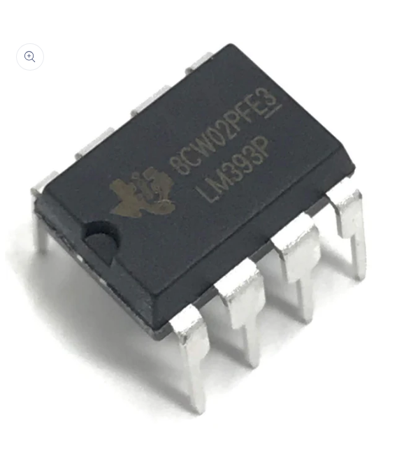
The LM393P is a dual differential voltage comparator integrated circuit (IC) from Texas Instruments. It contains two independent voltage comparators designed to operate from a single power supply over a wide range of voltages. These comparators are commonly used in applications such as zero-crossing detectors, voltage level detectors, and oscillator circuits.
Key Features
- Dual Comparator: Contains two independent voltage comparators in a single package.
- Wide Supply Voltage Range: Operates from a single supply of 2V to 36V or dual supplies of ±1V to ±18V.
- Low Input Offset Voltage: Typically around 2mV, with a maximum of 5mV at 30V supply voltage.
- Low Input Bias Current: Maximum of 250nA at 5V supply voltage.
- Open-Collector Output: Allows for wired-AND connections and operation with pull-up resistors.
- Low Supply Current: Typical quiescent current of 0.225mA per comparator.
- Fast Response Time: Typical propagation delay of 1.3µs.
- Common-Mode Input Voltage Range Includes Ground: Suitable for single-supply applications.
- Output Compatibility: Compatible with TTL, MOS, and CMOS logic levels.
Package Information
- Package Type: 8-pin PDIP (Plastic Dual In-line Package).
- Operating Temperature Range: 0°C to 70°C.
Pin Configuration (Top View)

Mouseover to Zoom
- 1OUT: Output of comparator 1.
- 1IN-: Inverting input of comparator 1.
- 1IN+: Non-inverting input of comparator 1.
- GND: Ground.
- 2IN+: Non-inverting input of comparator 2.
- 2IN-: Inverting input of comparator 2.
- 2OUT: Output of comparator 2.
- VCC: Positive power supply.
Applications
- Voltage Level Detection: Detecting when an input voltage crosses a specific threshold.
- Zero-Crossing Detectors: Identifying when an AC signal crosses zero voltage.
- Oscillator Circuits: Generating waveforms for timing applications.
- Pulse Width Modulation (PWM) Circuits: Controlling power delivery in applications like motor control.
- Battery Voltage Monitoring: Monitoring battery levels to prevent over-discharge.
Comparison with LM358P
While both the LM358P and LM393P are dual-channel ICs, they serve different functions:
- LM358P: Dual operational amplifier, suitable for analog signal amplification and processing.
- LM393P: Dual voltage comparator, designed to compare input voltages and output a digital signal indicating which input is higher.
The LM358P's outputs can swing closer to the negative rail, making it suitable for single-supply operations, whereas the LM393P has open-collector outputs, requiring pull-up resistors for proper operation.
IC Index
-
UA741
Mouseover to Zoom
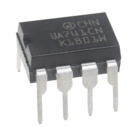
The UA741 is a classic general-purpose operational amplifier (op-amp) widely used in analog electronics since its introduction in the early 1970s. It remains popular for educational purposes and in legacy designs due to its simplicity, robustness, and well-documented behavior.
Key Features
- Offset-Voltage Null Capability: Allows fine-tuning of the input offset voltage using external potentiometers connected to the offset null pins.
- Internal Frequency Compensation: Equipped with a built-in 30 pF compensation capacitor, ensuring stability without the need for external components.
- Short-Circuit Protection: Designed to withstand output short circuits, enhancing its durability in various applications.
- No Latch-Up: Engineered to prevent latch-up conditions, contributing to reliable operation.
- Wide Input Voltage Range: Features a large common-mode input voltage range, making it suitable for various signal levels.
Electrical Specifications
- Supply Voltage Range: ±5 V to ±22 V (dual supply) or 10 V to 44 V (single supply)
- Input Offset Voltage: Typically 1 mV; adjustable up to ±15 mV
- Input Bias Current: Typically 80 nA
- Slew Rate: 0.5 V/µs
- Gain Bandwidth Product: 1 MHz
- Output Voltage Swing:
- ±12 V to ±14 V with a 10 kΩ load
- ±10 V to ±13 V with a 2 kΩ load
- Output Short-Circuit Current: Typically ±25 mA; maximum ±40 mA
- Operating Temperature Range: 0°C to 70°C
Pin Configuration (Top View)
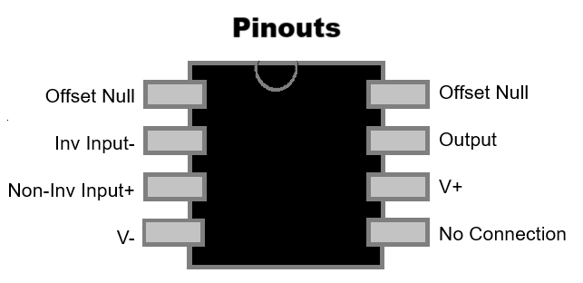
The UA741CN is a commonly used 8-pin dual in-line package (DIP) version of the UA741 op-amp. Here's a detailed breakdown of each pin:
Mouseover to Zoom
- Offset Null: Used with Pin 5 to null (adjust) the input offset voltage
- Inverting Input (-): Signal applied here is inverted at the output
- Non-Inverting Input (+): Signal applied here appears in-phase at the output
- V- (Negative Supply): Connect to the negative voltage rail (e.g., -15V in ±15V systems)
- Offset Null: Used with Pin 1 to null input offset voltage (typically with a 10k potentiometer)
- Output: The output voltage of the op-amp
- V+ (Positive Supply): Connect to the positive voltage rail (e.g., +15V)
- No Connection (NC): Not internally connected; often left floating
Package Options
- PDIP-8: Standard 8-pin Dual In-line Package
- SOIC-8: 8-pin Small Outline Integrated Circuit
- SO-8: 8-pin Small Outline package
Limitations
While the UA741 is versatile, it has some limitations:
- Not Rail-to-Rail: The output voltage swing does not reach the supply rails, which can be a constraint in low-voltage applications.
- Moderate Slew Rate: The 0.5 V/µs slew rate may not be sufficient for high-speed applications.
- Input Bias Current: Higher than that of modern op-amps, which can affect precision in certain circuits.
Modern Alternatives
For applications requiring improved performance, consider these modern op-amps:
- TL072: Offers lower noise and higher bandwidth.
- OP07: Provides ultra-low offset voltage and bias current for precision applications.
- NE5532: Suitable for high-fidelity audio applications due to its low distortion.
- LM324: Features low power consumption and is ideal for battery-powered devices
Common Applications
- Voltage Followers: Buffering signals without amplification.
- Summing Amplifiers: Combining multiple input signals.
- Integrators and Differentiators: Performing mathematical integration and differentiation of signals.
- Active Filters: Implementing frequency-selective circuits.
- Function Generators: Generating various waveform signals.
IC Index
-
PC817 - Optocoupler (Optoisolator)
Mouseover to Zoom
Purpose
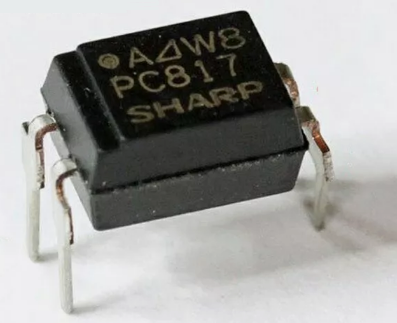
The PC817 is a commonly used optocoupler (also known as an opto-isolator) manufactured by Sharp and several other companies. It is designed to electrically isolate one part of a circuit from another while allowing signal transmission through light.
Overview
- Component Type: Optocoupler / Opto-isolator
- Package: 4-pin DIP (Dual Inline Package)
- Internal Structure: Infrared LED and phototransistor
- Isolation Voltage: Typically 5,000 Vrms
Common Uses:
Microcontroller interfacing, switching power supplies, signal isolation, protecting low-voltage logic from high-voltage systems
Pin Configuration (DIP-4)
       +--------+
 LED A | 1    4 | Transistor Collector
 LED C | 2    3 | Transistor Emitter
       +--------+
Pin 1: Anode (input LED)

Pin 2: Cathode (input LED)

Pin 3: Emitter (output transistor)

Pin 4: Collector (output transistor)
Electrical Characteristics (Typical)
| Parameter | Value |
|---|
| Forward Voltage (LED) | 1.2V (typical), 1.4V max |
| Input Current (If) | 10 mA to 20 mA recommended |
| Collector-Emitter Voltage (Vce) | 80V max |
| Collector Current (Ic) | 50 mA max |
| Current Transfer Ratio (CTR) | 50% to 600% (depending on variant, e.g. PC817A, B, C, D) |
| Isolation Voltage | 5000 Vrms |
| Response Time | Rise/Fall ~ 4-18 µs |
How It Works
- Input Side: You apply a current to the LED (Pins 1 and 2), causing it to emit infrared light.
- Output Side: The phototransistor (Pins 3 and 4) detects this light and conducts, passing a signal to the next stage of the circuit.
- Since the LED and phototransistor are optically coupled but electrically isolated, the input and output circuits do not share a direct electrical connection.
Applications
- Microcontroller isolation (e.g., between Arduino/Raspberry Pi and high-voltage AC circuits)
- Switching devices such as TRIACs or MOSFETs
- Digital logic level shifting
- Switch-mode power supplies
- Industrial equipment control
Example Circuit
Microcontroller GPIO ----> [220Ω] ----> |>| PC817 LED
                                        |
                                  PC817 phototransistor
                                        |
                                     [10kΩ]
                                        |
                                     GND
This circuit shows a typical way to use the PC817 to detect a GPIO signal on one side and use the transistor side to control another isolated circuit.
IC Index
-
Mouseover to Zoom
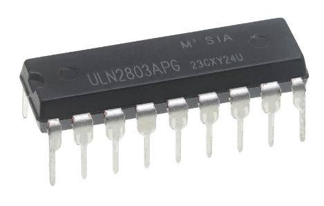
ULN2803 - Darlington Transistor Array (8-Channel)
Purpose:
The ULN2803 is an 8-channel Darlington transistor array IC, commonly used to drive high-current loads such as relays, lamps, or motors from low-level (logic-level) digital outputs e.g., from microcontrollers. Each of its 8 channels can sink up to 500 mA.
Overview
- Type: Darlington transistor array
- Channels: 8 independent NPN pairs
- Package: 18-pin DIP or SOIC
- Use Case: Interface low-power logic to high-power loads
Key Features
| Feature | Value/Description |
|---|
| Logic Input Voltage | TTL/CMOS compatible (5V logic safe) |
| Output Voltage (max) | Up to 50V |
| Output Current (per channel) | Up to 500 mA continuous |
| Internal Flyback Diodes | Yes (for inductive load protection) |
| Input Current (per channel) | ~1.35 mA (at 5V input) |
| Darlington Configuration | High gain, low base current |
Each input controls a Darlington pair, which means two transistors are cascaded to allow high current switching with low input current.
        +--------------+
 IN1  -| 1          18 |- OUT1
 IN2  -| 2          17 |- OUT2
 IN3  -| 3          16 |- OUT3
 IN4  -| 4          15 |- OUT4
 IN5  -| 5          14 |- OUT5
 IN6  -| 6          13 |- OUT6
 IN7  -| 7          12 |- OUT7
 IN8  -| 8          11 |- OUT8
 GND  -| 9          10 |- COM (flyback diode common)
        +--------------+
| Pins | Description |
|---|
| 1-8 | Logic inputs (connect to microcontroller or logic output) |
| 11-18 | Corresponding open-collector outputs |
| 9 | Ground |
| 10 (COM) | Connect to supply voltage (e.g. +12V) for flyback diodes to work |
How It Works
- A high signal (e.g., 5V) on an input pin turns on the corresponding Darlington pair.
- This sinks current through the output pin, switching the connected load (e.g., turning on a relay).
- The COM pin connects to the load's supply voltage (for clamping inductive spikes).
Applications
- Relay driving
- LED matrix and display driving
- Stepper motor control
- Solenoid control
- Interfacing microcontrollers with 12V or 24V loads
Example Use
Driving an LED from a 12V supply:
5V MCU Output ---> IN1 (Pin 1)
                  |
              ULN2803
                  |
             OUT1 (Pin 18) ---> LED ---> 12V
                                |
                              GND
Don't forget: Connect COM (Pin 10) to 12V (same as LED supply) to activate the internal flyback diode.
Alternatives
- ULN2003 - 7-channel version (used in some stepper motor kits)
- TBD62783 - Toshiba equivalent with slightly higher ratings
- Discrete NPN transistors - Custom drivers if fewer channels are needed
IC Index
-
Mouseover to Zoom
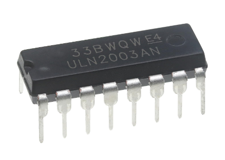
ULN2003APG - Darlington Transistor Array (7-Channel)
Purpose:
The ULN2003APG is a 7-channel Darlington transistor array IC designed to interface low-power digital logic signals (e.g. microcontrollers) with higher-power loads like relays, lamps, stepper motors, and LEDs. It's known for its high voltage and current capabilities, making it suitable for handling larger loads.
It's functionally similar to the ULN2803 but with 7 channels instead of 8, and is very commonly found in 28BYJ-48 stepper motor driver boards.
Overview
- Full Name: ULN2003APG
- Type: Darlington transistor array
- Channels: 7 NPN Darlington pairs
- Package: 16-pin DIP or SOP (APG = DIP variant)
- Manufacturer: Toshiba (others produce compatible versions)
Key Features
| Feature | Description |
|---|
| Input logic level | TTL/CMOS compatible (e.g., 5V MCU) |
| Output voltage (max) | 50V |
| Output current (max/channel) | 500 mA (can sink current only) |
| Flyback diodes | Built-in (for driving inductive loads) |
| Output type | Open collector (requires external load) |
| Common freewheeling diode pin | Yes, via COM (Pin 9) |
Pinout (DIP-16)
        +--------------+
 IN1  -| 1          16 |- OUT1
 IN2  -| 2          15 |- OUT2
 IN3  -| 3          14 |- OUT3
 IN4  -| 4          13 |- OUT4
 IN5  -| 5          12 |- OUT5
 IN6  -| 6          11 |- OUT6
 IN7  -| 7          10 |- OUT7
 GND  -| 8           9 |- COM (diode common)
        +--------------+
| Pins | Description |
|---|
| 1 - 7 | Logic inputs |
| 10 - 16 | Corresponding open-collector outputs |
| 8 | Ground |
| 9(COM) | Connect to +V (e.g., 12V) to use internal flyback diodes |
How It Works
- Each channel is a Darlington pair, amplifying the input signal to switch high-current loads.
- Output goes LOW (sinks current) when input is HIGH.
- Built-in diodes protect against voltage spikes from inductive loads like motors.
Common Applications
- Driving relays and solenoids
- Controlling LED strips or high-brightness LEDs
- Interfacing stepper motors (like 28BYJ-48)
- Switching small DC motors
- General-purpose logic-to-load interfacing
Example Use: Stepper Motor Driver
The ULN2003APG is used in many stepper motor driver boards like:
- Input Pins 1-4 connected to a microcontroller (e.g., Arduino digital pins)
- Output Pins 16-13 connected to the four coils of a 28BYJ-48 stepper motor
- Pin 9 (COM) connected to +5V motor supply
- Pin 8 (GND) connected to logic and motor ground
Related Versions
| Part | Channels | Input Voltage | Common Use |
|---|
| ULN2003A | 7 | TTL/CMOS | General-purpose |
| ULN2803A | 8 | TTL/CMOS | Wider application |
| ULQ2003 | 7 | CMOS only | Used in some logic families |
Summary
The ULN2003APG is a reliable, simple-to-use 7-channel switching IC ideal for:
- Driving relays and motors
- Controlling outputs from 5V or 3.3V microcontrollers
- Handling moderate-current loads with flyback protection
IC Index
-
Mouseover to Zoom
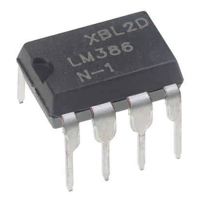
LM386 - Audio Amplifier
Purpose:
The LM386 is a low-voltage audio power amplifier. Commonly used to amplify low-level audio signals from microphones or audio sources to drive small speakers, typically in battery-powered consumer devices. It's simple to use, requires few external components, and can drive small speakers directly
Overview
- Type: Low-voltage audio amplifier
- Output Power: ~0.325W (at 6V, 8Ω speaker)
- Operating Voltage: 4V to 12V (or up to 18V max, depending on variant)
- Gain: Internal gain of 20; externally adjustable up to 200
- Package: 8-pin DIP, SOIC
Key Features
| Feature | Value/Description |
|---|
| Voltage Supply Range | 4V to 12V (LM386N-1), up to 18V (N-4) |
| Output Power | ~325 mW into 8Ω at 6V supply |
| Input Impedance | ~50 kΩ |
| Current Draw (idle) | ~4 mA |
| Adjustable Gain | 20 (default), 26-200 with external parts |
| Speaker Drive Capable | Yes, directly drives 4Ω-32Ω speakers |
| Low external parts | Needs just a few capacitors/resistors |
Pinout (DIP-8 or SOIC-8)
       +--------+
  Gain | 1    8 | Vcc
  Gain | 2    7 | Bypass
  GND  | 3    6 | Output
 Input | 4    5 | Vbias (input)
       +--------+
| Pins | Description |
|---|
| 1 & 8 | Gain control - place a capacitor between them to increase gain |
| 2 | Inverting input |
| 3 | Ground |
| 4 | Non-inverting input |
| 5 | Output |
| 6 | Power supply (Vcc) |
| 7 | Bypass (optional decoupling capacitor to reduce noise) |
| 8 | Gain control (see Pin 1) |
Gain Configuration
- No capacitor between pins 1 & 8: Gain = 20 (default)
- 10 µF capacitor between pins 1 & 8: Gain = 200
- Capacitor + resistor: Custom gain (intermediate values)
Example Circuit (Basic Audio Amp)
[Audio Input] ---[10kΩ pot]---> Pin 3 (Non-inverting input)
                             |
                            GND
| Pin | Description |
|---|
| 6 | +6V to +9V supply |
| 4 | GND |
| 5 | Output to speaker (via 220 µF cap) |
| 1 & 8 | Optional 10 µF cap for gain boost |
Applications
- Portable audio devices
- Signal amplification for radios or media players
- DIY guitar or microphone amps
- Toys and learning kits
- Battery-powered alarms or buzzers
Summary
The LM386 is a small, versatile, low-power amplifier ideal for:
- Small speaker output (headphones or low-watt speakers)
- Operating directly from batteries
- Minimal component count designs
It's a favorite among hobbyists and educators for basic audio projects.
IC Index
-
Mouseover to Zoom
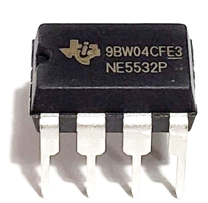
NE5532 - Low-Noise Dual Op-Amp
Purpose:
The NE5532 is a low-noise, high-performance dual operational amplifier (op-amp) widely used in audio, instrumentation, and signal-processing applications. It offers excellent audio fidelity and low distortion, making it a favorite in high-end audio equipment.
Overview
- Component Type: Dual Operational Amplifier (2 op-amps in one IC)
- Package: 8-pin DIP, SOIC, or other surface-mount options
- Manufacturer: Originally Philips/Signetics, now made by multiple vendors (TI, ST, ON, etc.)
- Primary Features: Low noise, high slew rate, low distortion
Key Electrical Characteristics (Typical)
| Parameter | Value |
|---|
| Supply Voltage (Vcc) | ±3V to ±20V (or 6V to 40V single supply) |
| Input Offset Voltage | 0.5 mV (typical) |
| Input Bias Current | 200 nA |
| Gain Bandwidth Product | 10 MHz |
| Slew Rate | 9 V/µs |
| Total Harmonic Distortion (THD) | 0.0005% |
| Input Noise Voltage | 5 nV/√Hz |
| Output Current | ±38 mA |
Notable Features
- Low Noise: Excellent for microphone preamps, phono stages, and other sensitive audio applications.
- Dual Op-Amps: Two independent, high-performance op-amps in a single IC.
- Unity Gain Stable: Suitable for buffer configurations.
- Low Distortion: Ideal for hi-fi audio and analog signal processing.
- High Output Drive Capability: Can drive low-impedance loads (e.g., 600Ω headphones or mixers).
Pin Configuration (DIP-8 / SOIC-8)
       +--------+
  Out A| 1    8 | V+
  -In A| 2    7 | Out B
  +In A| 3    6 | -In B
   V-  | 4    5 | +In B
       +--------+
- Pins 1, 2, 3: Output A, Inverting Input A, Non-inverting Input A
- Pins 5, 6, 7: Non-inverting Input B, Inverting Input B, Output B
- Pin 4: Negative supply (V-)
- Pin 8: Positive supply (V+)
Typical Application Circuits
- Audio Line Driver (Unity Gain Buffer)
Audio Input ---> +IN
                 -IN <--- Connected to Output
Audio Output <--- OUT
- Inverting Amplifier
Vin ---> [R1] ---> -IN
                   |
                [R2]
                   |
                 OUT ---> Vout = - (R2/R1) * Vin
+IN connected to GND or virtual ground
Applications
- High-fidelity audio amplifiers
- Mixing consoles
- Equalizers and filters
- Pre-amplifier circuits
- Analog signal conditioning
- Active filters and integrators
NE5532 vs Other Op-Amps
| Op-Amp |
Noise (nV/√Hz) |
Slew Rate (V/µs) |
Bandwidth |
Audio Quality |
| NE5532 |
5 |
9 |
10MHz |
     |
| TL072 |
18 |
13 |
3MHz |
   |
| LM358 |
40 |
0.5 |
1MHz |
 |
| OPA2134 |
8 |
20 |
8MHz |
     |
(nV/√Hz) represents spectral noise density, specifically the amount of root-mean-square (RMS) noise voltage per square root Hertz. It indicates how much noise voltage is present per unit bandwidth, specifically per square root of Hertz. This unit is commonly used to characterize noise in electronic components like operational amplifiers (op-amps) and low-noise amplifiers.
Summary
The NE5532 is a workhorse op-amp in audio engineering, known for its:
- Low noise
- Low distortion
- High fidelity performance
- Dual amplifier layout
It strikes an excellent balance between performance and cost, which is why it's still popular decades after its introduction.
IC Index
© 2025 Professor Petabyte
 There are many types of standard ICs, each type serves a particular purpose. They most (but not all) have a similar general layout. At one end is a mark or indentation that indicated where the 'top' of the IC is, and the pins are numbered anticlockwise from that point. Where the indicator is not a central notch, it usuallu is closest to pin 1 of the IC. The type of IC, and sometimes (not always) the name of the manufacturer is printed on the IC.
 ←Index


