Mouseover to Zoom
 ←Index
by Professor Petabyte
The GPIO 'General Purpose Input/Output' pins are the primary communication channels for the Raspberry Pi Pico; Primary because the Pico can also transmit and receive data via WiFi and Bluetooth. Only GPIO0 to GPIO22 and GPIO26 to GPIO28 are brought out to physical pins on the Pico board.
GPIO23 and GPIO24 on a Raspberry Pi Pico are General Purpose Input/Output pins that can be used for digital input or output, as well as various alternate functions (like UART, SPI, PWM, etc.), so whilst they do exist internally and are usable are not connected to any physical header pins on the Pico, so unless you're working directly with the RP2040 chip on a custom board, GPIO23 is not accessible on a regular Pico.
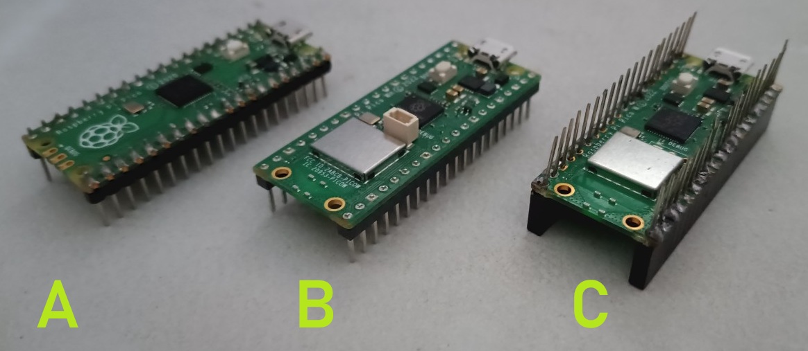
Picture on right shows three Raspberry Pi Picos. Pico 'A' is an original Pico with header pins soldered on. Pico 'B' is a Pico WH, meaning it has WiFi capability (notice the silver square where the Raspberry logo is on Pico 'A') and pre-soldered headers, and Pico 'C' is another Pico W but with custom header pin connectors - female below the board, and male above it. The Pico and Pico2 are available in several variants suffixed with W, H or WH. W indicates Wifi on board, and H means header pins are pre-soldered (i.e. attached before delivery, avoiding the tedious task of soldering them on by hand).
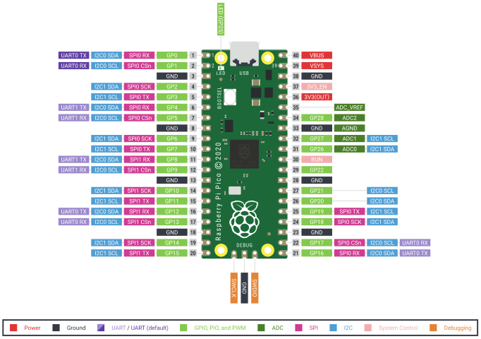
On the Raspberry Pi Pico, GPIO23 and GPIO24 correspond to:
| GPIO | Physical Pin | Typical Label on Pico Pinout |
|---|---|---|
| GPIO23 | Pin 35 | GP23 |
| GPIO24 | Pin 36 | GP24 |
By default, these are digital I/O pins, meaning you can:
GPIO Pins 23 & 24 can be configured to have alternate functions using MicroPython, C/C++, or CircuitPython. e.g.
from machine import Pin

led = Pin(23, Pin.OUT)
led.toggle()
GPIO25 is a very special pin. It turns the onboard LED on/off. That's all. This is a handy feature for basic output tests, like blinking an LED. Even though it's tied to the LED, GPIO25 can still be used in any standard GPIO mode (HIGH/LOW output, input)
from machine import Pin
import time

led = Pin(25, Pin.OUT)

while True:
    led.toggle()
    time.sleep(0.5)
This can very useful if the Pico does not have a screen connected to report status and error conditions. The LED can be programmed to blink rapidly (on/off 0.25 second bursts) and then pause (off for 3 seconds) to enable the operator to differentiate different error conditions, e.g,
| Blinks | Condition |
|---|---|
| 1 | All is well - Running normally. |
| 2 | Unable to connect to Wifi |
| 3 | A peripheral is not responding |
| 4 | I am overheating! |
| ...and so on. | |
from machine import Pin
import time

led = Pin(25, Pin.OUT)

def BlinkCondition(blinks):
    for _ in range (blinks):
        led.on()
        time.sleep(0.2)
        led.off()
        time.sleep(0.2)
    time.sleep(3)
#
# Main program code here
# Code that makes Wifi connection
WiFiConnected=True

while True:
#
#   Code that makes Wifi connection
#   For this example, assume WiFi connected OK
    WiFiConnected=True
#   #Report unable to connect to Wifi
    if not WiFiConnected:
        BlinkCondition(2)
    else:
        #Change to SomethingFailed = True to see a failure simulation
        SomethingFailed = False
#		Report Error condition 4 on LED
        if SomethingFailed:
            BlinkCondition(4)
        # Loop Completed - All is well
        else:
            BlinkCondition(1)
Above is an example Micropython program which uses the LED on GPIO to report program status. Normal running is shown by 1 flash, WiFi connection failed by 2 flashes, and something else failing by 4 flashes.
Raspberry Pi Pico does expose GPIO26, 27, and 28, and they have special features
| GPIO | Physical Pin | Special Function | Usable as Digital I/O? | Usable as Analog In? |
|---|---|---|---|---|
| GPIO26 | Pin 31 | ADC0 (Analog In 0) | Yes | Yes |
| GPIO27 | Pin 32 | ADC1 (Analog In 1) | Yes | Yes |
| GPIO28 | Pin 34 | ADC2 (Analog In 2) | Yes | Yes |
These are digital I/O pins, just like others (HIGH/LOW, input/output). Additionally, they are connected to the RP2040's 12-bit ADC:
from machine import ADC, Pin

adc = ADC(Pin(26))  # Reads from GPIO26 / ADC0
value = adc.read_u16()  # Returns 0-65535 (12-bit reading scaled to 16-bit)
print("Analog value:", value)
GPIO29 is also usable for ADC, but it's shared with the internal temperature sensor, so it's a special case.
ADC inputs are not 5V tolerant — apply only 0-3.3V.
The Pico2 shares the same pinouts as the original Pico. The differences lie in different areas:-
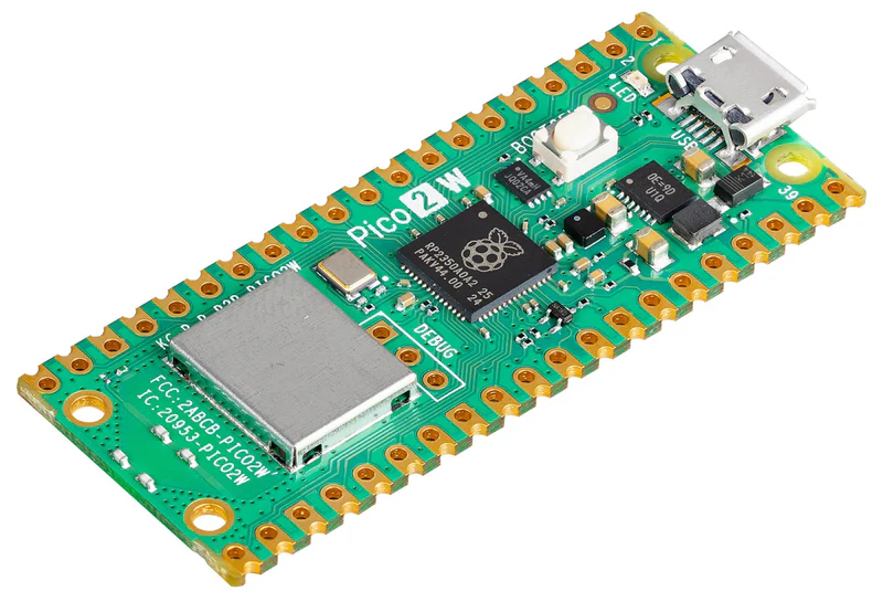
The Raspberry Pi Pico 2 W is a wireless version of the Raspberry Pi Pico 2, offering 2.4GHz 802.11n wireless LAN and Bluetooth 5.2. At the heart of the board is the Raspberry Pi RP2350, Raspberry Pi's high-performance, secure microcontroller chip, successor to the popular RP2040 microcontroller first seen on the original Raspberry Pi Pico.
Compared to the original Raspberry Pi Pico, the RP2350-based Raspberry Pi Pico 2 W offers a higher core clock speed, double the on-chip SRAM, double the on-board flash memory, more powerful Arm cores, optional RISC-V cores, new security features, and upgraded interfacing capabilities! These significant performance and feature improvements are delivered with the same form factor and are software-compatible with the original Raspberry Pi Pico series boards, with the same GPIO pinout and micro-USB connector for power and programming, allowing easy upgrade of original Pico projects and re-use of all Raspberry Pi Pico add-ons, cables and accessories.